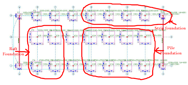
In our previous tutorial on foundations, we dealt with the design of pad foundations underneath columns. Over the course of our next three tutorials, beginning with this, we will do so for other types of foundations which are strip, pile cap and raft foundations respectively.
To achieve this in our tutorial, we will apportion some of the previously designed pad foundations into the other types listed above as shown in the diagram below.
Step 1:
Double click ‘Storey: St00’ in the Structure tree view on the left side of the screen to get the whole view of all our previously designed foundations.

Since we have already designed for pads, next, we design for strip foundations. Firstly, we will delete the pad foundations in the area marked out for the strip foundation. In Orion 18, beams are required to design strip foundations. Since we originally don’t have beams in our foundations, we will create beams for the strip foundations
NB:
Building Analysis of the building has to be done before we can proceed with the design of foundation.In the case of our tutorial, we have already done that previously. For the beams, we will create it using the properties as shown in the dialog box below. The depth of the beams created 'h' will be the depth of the strip foundation.
Step 2:
While holding ‘ctrl’, select all the beams, then right click and select ‘Insert Strip Footing’. A ‘STRIP FOOTING – Project: LearningOrion’ dialog box appears. Tick the ‘Design Envelope’ box at the top of the dialog box. Click ‘Calculate’ to design the strip foundation based on the parameters in the dialog box.
Step 3:
In the ‘Strip Footings Results – Footing 3’ dialog box that appears, you can check the values for axial load, moment as well as Shear, span moments and support moments used for the design. Click on the ‘Diagrams’ tab to see the loading, shear force and bending moment diagrams for the foundation as shown below. The results can also be printed using the buttons at the top right hand side of the dialog box. Click ‘OK’ to return to the design area.
Step 4:
Next, we will design the foundation. To do that, we select ‘Run’ --‘Beam Section Design and Detailing’ -- ‘Create/Update Footing Beam Records’ in the main menu. Click ‘Yes’ in the dialog box that appears. This updates the values of the footing analysis so that it can be used for Foundation beam Design.
Next, we select ‘Run’ – ‘Beam Section Design and Detailing’ – ‘Foundation Beams’ to design the strip foundation as a Foundation beam. The rest of the design is then carried out as was done for Storey beams in our earlier tutorial.
For comments and questions, you can reach us through the contact form below. You can also subscribe to receive our weekly newsletters so that you never miss a thing.
ORION 18: HOW TO MODEL AND DESIGN STRIP FOUNDATIONS
 Reviewed by Izuchukwu Obi
on
13:52:00
Rating:
 Reviewed by Izuchukwu Obi
on
13:52:00
Rating:


How can I change steel grades from T(xx)mm to Y(xx)mm
ReplyDeleteCharles, In Orion 18, T is used to represent steel Grade 460. It uses Y to represent steel grade 410. Therefore, the only way to change it from T to Y is to change the steel grade.
ReplyDeleteThanks
ReplyDeletethank you so much
ReplyDelete